Design and Specification
Most of the installation is decided in the design, not on site. This section and those that follow adapt the rules of TS 13902, the sandwich panel application standard, to Nuhpanel products. The binding text is the standard itself.
Roof pitch
At least 7% where a single panel spans from ridge to valley, and at least 10% where two or more panels are used. On a roof with transverse joints, water stays longer on the lap line, so the pitch increases. Nuhpanel roof panels are produced in one piece up to 15.5 m, so most projects need no transverse joint at all.
Loads
Wind and snow loads are calculated to TS 498 for the region of the project. The panel section and the purlin spacing follow from that calculation; panel thickness alone does not give a load value. Distributed load and limit values by family are in the Load Tables section.
Colour and panel length
Dark panels absorb a larger share of solar radiation; the outer sheet warms and expands while the inner sheet does not expand as much, and the panel works. Panel lengths are therefore shorter in dark colours:
| Panel | Light colour | Dark colour |
|---|---|---|
| PUR-PIR wall and cold room | 12.00 m | 6.00 m |
| PUR-PIR roof | 13.60 m | 10.00 m |
| Rock wool / glass wool wall | 10.00 m | 6.00 m |
| Rock wool / glass wool roof | 12.00 m | 9.00 m |
| EPS wall | 12.00 m | 6.00 m |
| EPS roof | 13.60 m | 10.00 m |
The values are for 0.40/0.50 mm steel and 40 mm panel thickness. For other thicknesses and lengths, ask us.
Steel, coating and paint
Minimum steel thicknesses on a 40 mm panel: 0.50/0.50 mm for rock wool and glass wool, and 0.35/0.45 mm (inner/outer) for EPS, PUR and PIR. Galvanising is at least 100 g/m², and aluminium-zinc alloy at least 70 g/m². The outer face carries at least 5 microns of primer and 20 microns of paint, and the inner face at least 5 microns of primer.
The paint type follows the environment: polyester is not enough on the coast or in an industrial area. The detail is in the Metal, Coating and Colour section.
Fire
Products below class C-s3,d2 cannot be used. On roofs, panels that are not metal on both faces require a Broof classification to TS EN 13501-5. The classes and their equivalents are in the Fire Classes section.
Unloading and Lifting
A panel is handled twice before it reaches its place: when it is loaded at the factory and when it is unloaded on site. Most damage happens in those two moments, not during installation.
Unloading from the vehicle
Packs are unloaded with a crane or a forklift with suitable attachments. For packs longer than 7 m, a four-fork attachment is used; two forks bend the pack in the middle.
Steel rope and chain are not used on a crane. Flat nylon, silk or hemp slings at least 20 cm wide are used. Timber blocks are placed above and below where the sling touches the panel; the block projects 3.5 cm beyond both sides of the pack. If the sling is too short the load bears on the edges, the lap profiles are crushed, and that panel no longer keeps water out.
Packs longer than 6 m are lifted with a purpose-made spreader; the spreader cannot be shorter than half the shortest panel. One pack is lifted at a time and packs are never dragged.
Lifting onto the roof
Packs are not piled at a single span on the roof and are not stacked; they are distributed over the purlins. A stacked pack is a point load the structure was not designed for.
Taking panels from the pack
Once the pack is opened, the top panel is not dragged off. Each panel is lifted individually and not rubbed against the one below; rubbing scratches the paint of the lower panel.
A panel is not held by its lap or by its facing. The facing separates from the core and the panel loses its composite action at that point. Lifting is done with vacuum equipment or with enough people.
Storage
Panels deteriorate while waiting on site, not during installation.
Under cover
Packs to be stored unopened are kept in a closed, dry place. The floor should fall slightly (2-3%) so that water vapour does not condense inside the pack.
In the open
Where outdoor storage cannot be avoided, packs are kept at least 20 cm above the ground and covered with a UV-resistant tarpaulin. The tarpaulin is laid so that it does not block airflow: vapour builds up under tightly wrapped plastic and the panel corrodes from the inside.
Packs are not left in the open for more than a week and their moisture is checked daily. Packs are not stacked on one another and nothing is placed on top of them.
Soil, lime, mortar, fertiliser, acid, salt and alkali all lead to corrosion; contact with them is prevented.
Protective film
The film on the steel is there for transport and installation scratches, not for the sun. In sunlight the film bonds to the paint and lifts it when removed.
The film is removed immediately after installation and no later than 15 days from the production date. An opened pack is repacked at the end of the working day.
Roof Panel Installation
The performance of a panel is set by the detail closed on site, not by the value measured in the laboratory.
Direction and sequence
The structure is checked, the prevailing wind direction is established on site, and installation starts from the opposite side. A lap does not stand against the wind.
Laps and transverse joints
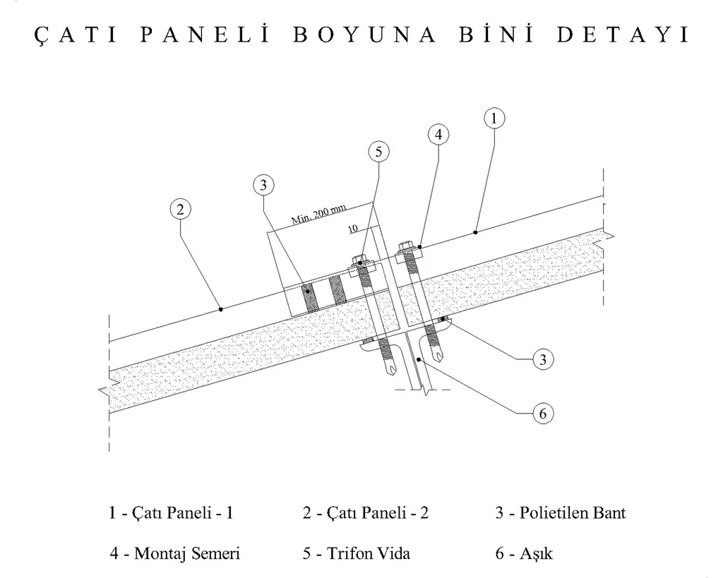
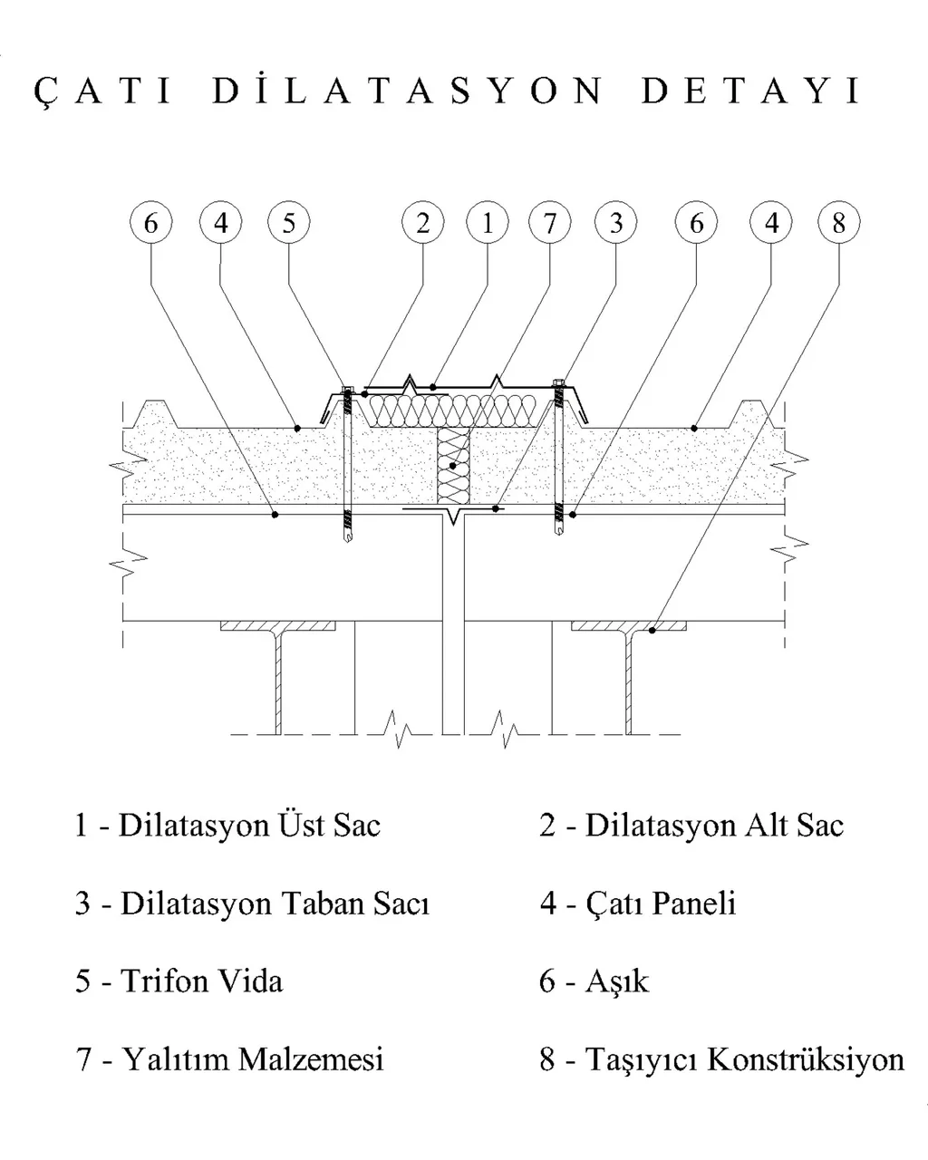
Where a transverse joint is needed, an expansion plate is placed over two purlins and fixed. Silicone tape or double-sided tape is run over the lower panel, in front of the screw line and preferably in front of and behind it. The upper panel laps the lower one by at least 20 cm.
Fixing
Screws are applied through the rib with a saddle profile, not through the rib crown; the saddle carries an EPDM gasket, matches the rib dimension and is at least 2 mm aluminium. Screws are not hammered but tightened to a set torque: an undertightened gasket does not hold water and an overtightened one deforms the sheet. Correct fixing is reached when the EPDM washer is compressed by about a quarter of its thickness. The driver is run at 1500-1800 rpm.
The inner sheet of the panel meets the purlin flush. On rock wool panels, fixing is made with a metal connection plate; a fibrous core does not hold a screw on its own.
Roof screw length: insulation thickness + rib height + purlin thickness + 20 mm.
Thermal bridges and corrosion
A 2-10 mm self-adhesive foam is applied where the structure meets the panel and where the panel meets an accessory. Direct metal-to-metal contact is both a thermal bridge and the start of corrosion.
Sealant is run along the edges of accessories, across and along, 2 cm in from the edge.
Ridges and valleys
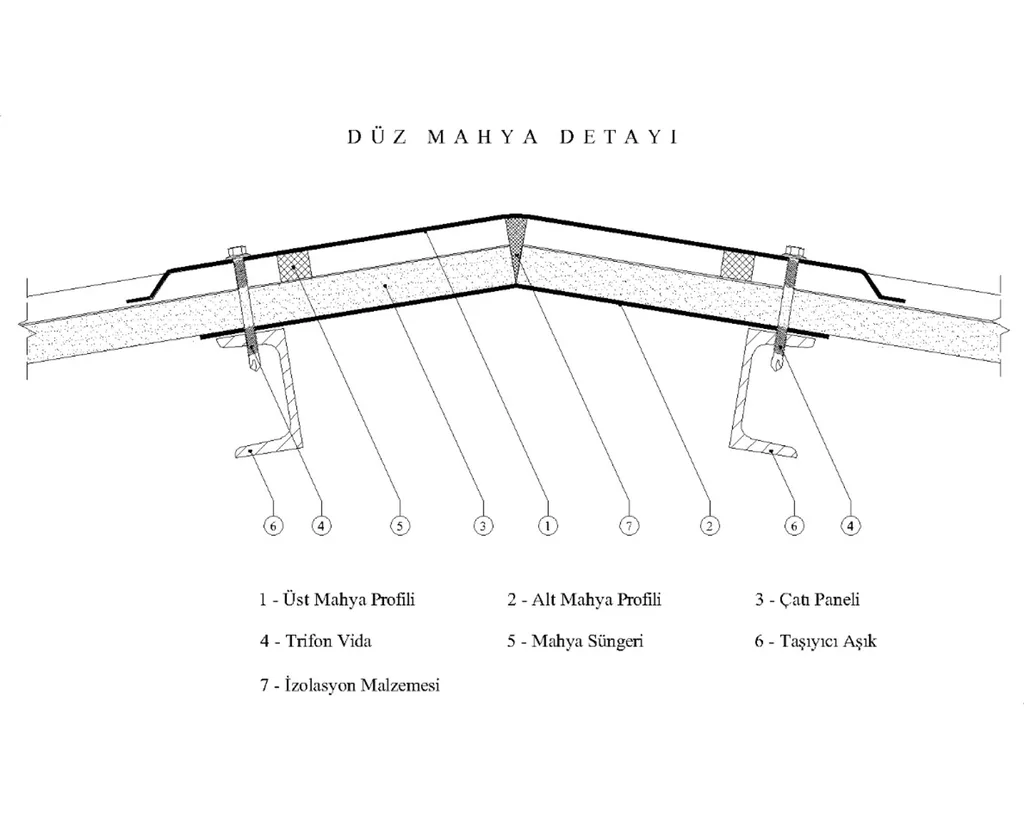
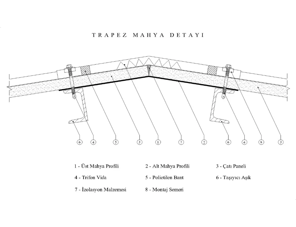
The lower ridge member is fixed to the purlins on both sides, the panels are screwed over it, and the gap at the ridge joint is filled with insulation. Before the upper ridge is placed, sealant or double-sided tape is applied 2 cm in from the ends.
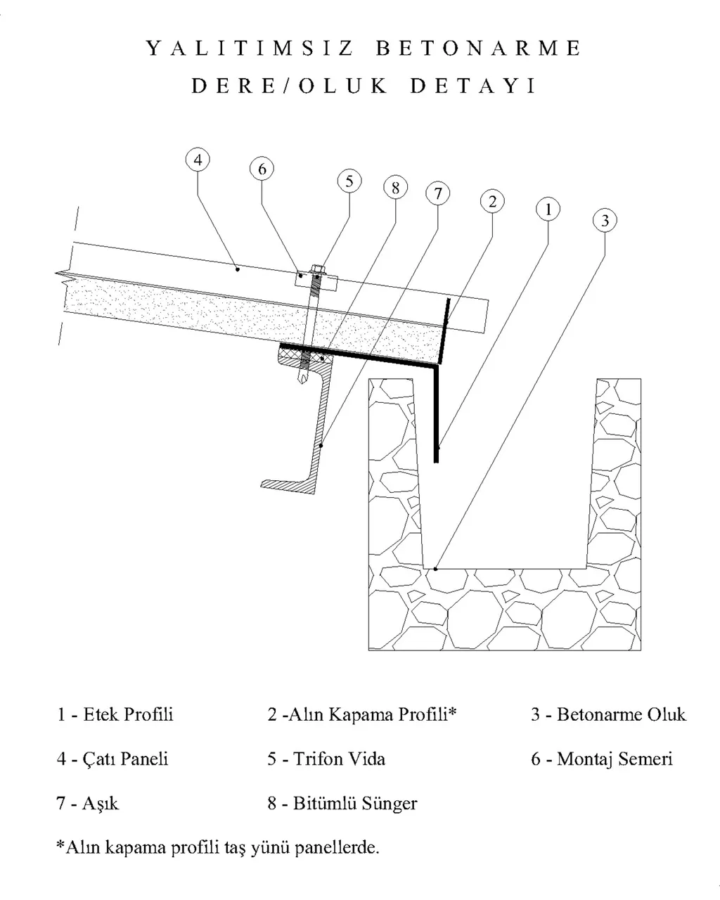
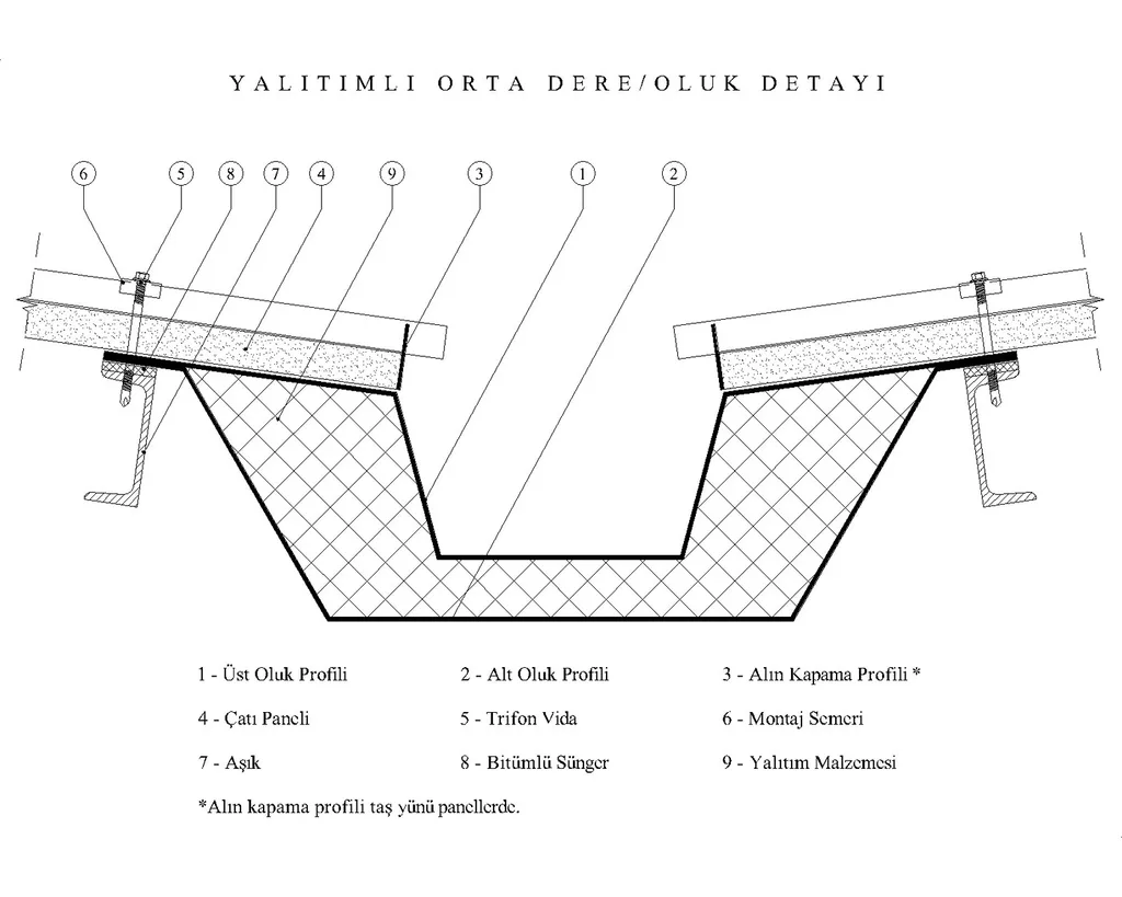
Waterproofing is applied inside every valley. Concealed and central valleys also require insulation beneath the valley.
Weather and cutting
To reduce thermal stress, an air temperature of +10 °C or above is recommended on the day of installation. Panels are not installed in high wind or rain.
Where a panel has to be cut, an abrasive disc is not used. The sparks burn through the galvanising and the paint at individual points, and those points corrode within a few years. Cutting is done with an electric saw or a nibbler.
Panels from the same production batch are laid on the same elevation; there can be a shade difference between panels produced at different times.
Wall Panel Installation
The rules on walls follow the same logic as on roofs; the differences are below.
Starting out
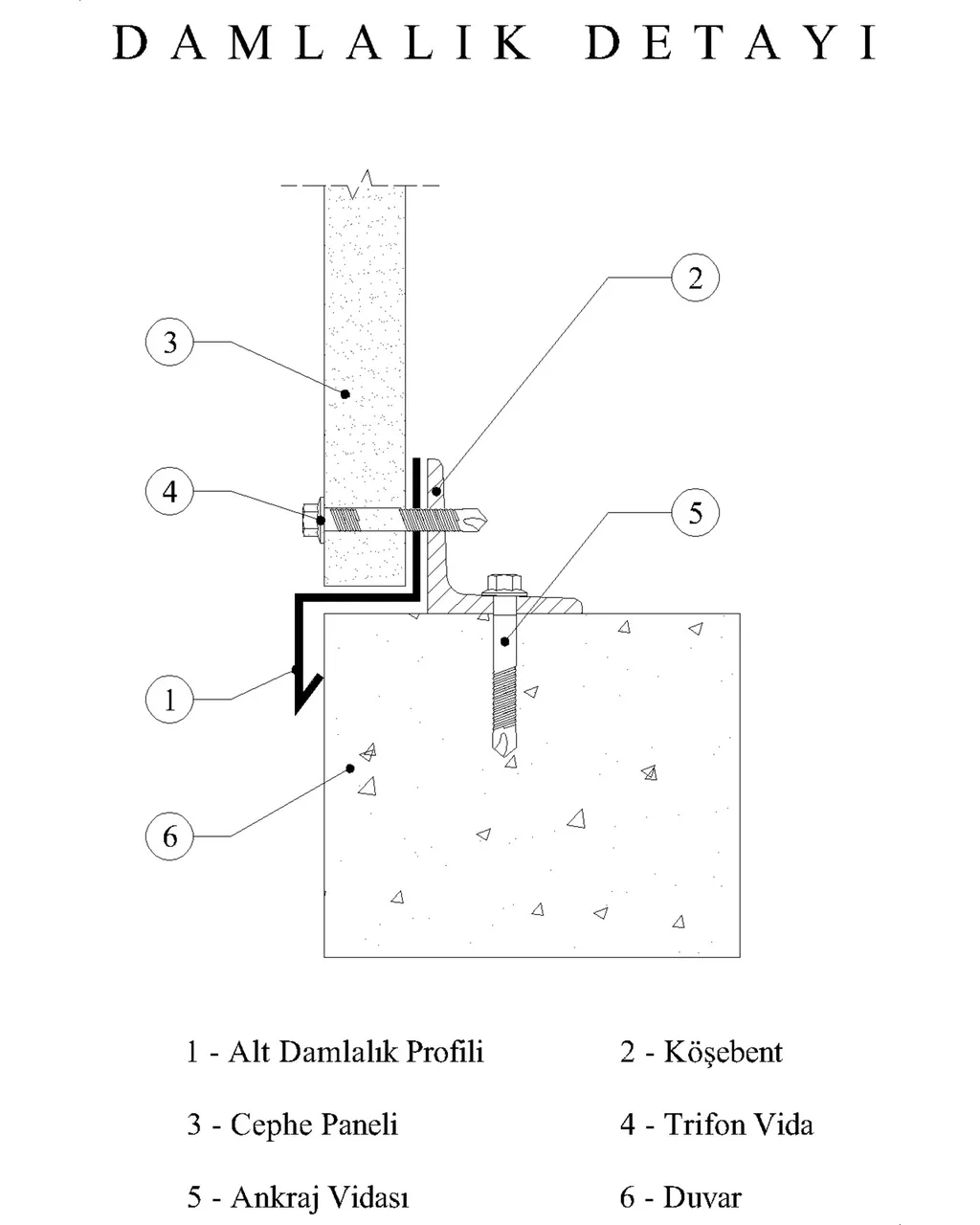
The structure is checked and the prevailing wind direction established. At the plinth level, a drip profile matching the panel thickness is fixed horizontally to the structure: this is what stops water working inwards from the lowest level.
Whether the panel is laid horizontally or vertically, work starts from the side opposite the prevailing wind, according to the joint detail.
Fixing
On a concealed-fix panel the screw stays inside the interlock channel and the next panel covers it, so no panel is started before the previous one is locked. On an exposed-fix panel the screw stays outside with its gasket, and is not tightened far enough to crush that gasket.
For concealed-fix work, the screw length is: the panel thickness at the fixing point + the substructure thickness + 20 mm.
The inner sheet of the panel meets the column or rail flush, and the form of the outer sheet is not deformed.
Surfaces
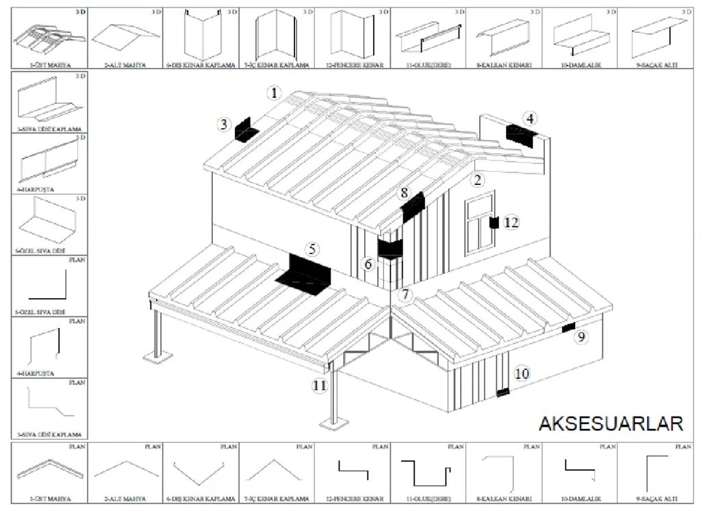
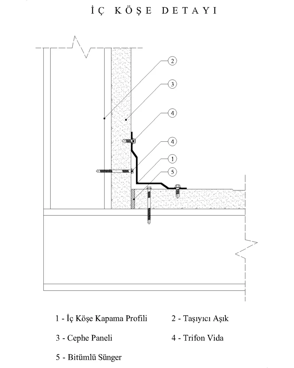
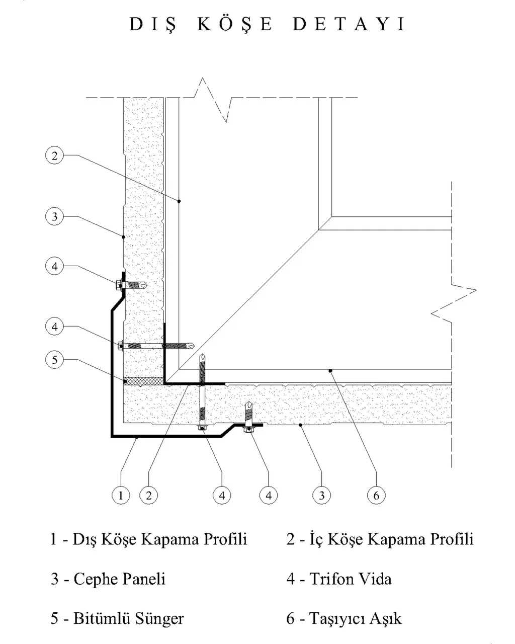
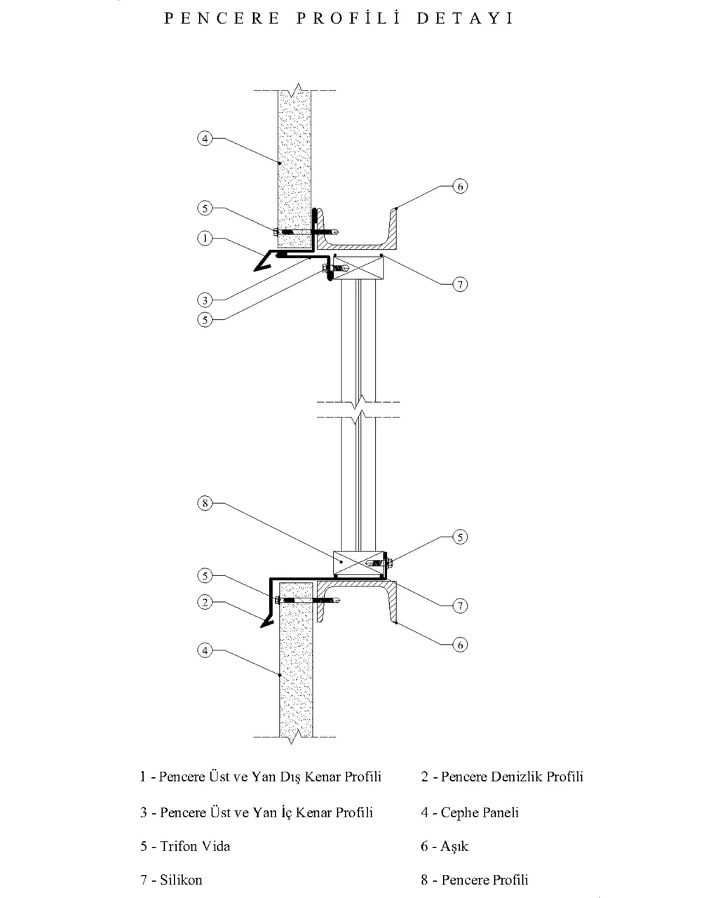
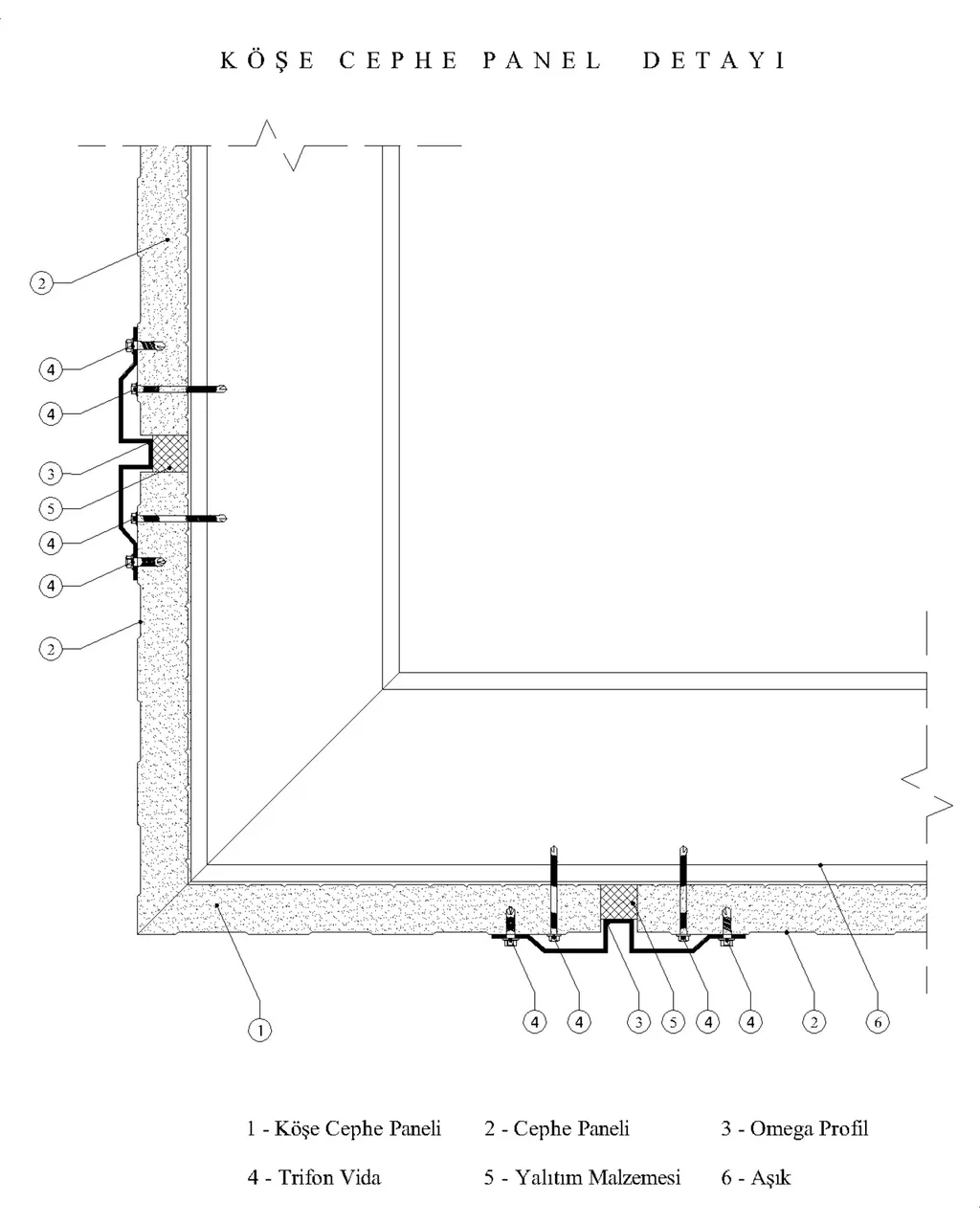
Once the protective films are removed, the installed surfaces are confirmed to belong to the same elevation. All accessories in the project are applied at internal and external corners and around doors and windows.
Where cutting and welding are done on site, flying swarf is prevented; swarf on the steel becomes a focus of corrosion.
An air temperature of +10 °C or above is recommended on the day of installation.
Partition Walls and Cold Rooms
The rules for wall installation apply to partition walls. Cold rooms and cold stores add further requirements.
Sequence
Installation begins with the walls, then the ceiling, and the floor last.
Sealing
A 2 mm gap for sealant is left at the panel joints; the joint channels are sealed with butyl sealant. Silicone is used in the joint between two panels; on surfaces where food is stored, food-safe silicone is required.
The protective polyethylene film is removed once installation is complete.
Floors and thermal bridges
Where the floor is to be insulated, the cold room area is designed as a lowered slab so that the finished level matches the surrounding floor.
In rooms below −5 °C, a narrow strip of the inner steel sheet is removed near the floor: otherwise the sheet forms a continuous thermal bridge between the floor and the room.
In blast chilling and frozen storage rooms, the floor is ventilated from below or fitted with heating elements so that the ground does not freeze and cause structural damage.
Refrigeration and electrical runs passing through the ceiling and walls are insulated so that they do not conduct heat.
Commissioning
The room is cooled gradually, and a freezer room carries enough pressure relief valves. A sudden pressure difference buckles the panel faces.
Fasteners and Ancillary Materials
However good a panel is, it does not outlive the screw that holds it in place.
Choosing the screw
Fasteners must meet the mechanical properties of TS EN ISO 3506-1 and hold an ETA or UTO certificate. The number, type and length of screws are set by the project; the drilling capacity must suit the thickness of the substructure. On steel structures, self-drilling screws are used.
Each screw is used with a stainless washer with an EPDM gasket of at least 16 mm diameter.
Corrosion category
The screw material is selected according to the environment the building stands in (TS EN ISO 12944-2):
| Environment | Example | Suitable screw |
|---|---|---|
| C1, very low | Indoor, dry | Galvanised carbon steel is sufficient |
| C2, low | Rural, very low salinity | Zinc plus organic coating, or stainless |
| C3, medium | Urban, industrial, 1000 m from the sea | Zinc plus organic coating, or stainless |
| C4, high | Coastal and industrial, 100-300 m from the sea | A4 (1.4404 / 316) and above |
| C5-I / C5-M | Severe industrial or marine | A5 (1.4529) |
For stainless fixings, bimetal screws are used, with a stainless body and a carbon steel drilling tip: a stainless tip cannot drill the substructure.
A test report is valid only if it gives the tensile and shear capacity of the whole connection, not of the screw alone.
Tapes, sealants and foams
These are the materials that seal the ridge, the joints and the side laps of the panel. Sealant applied in the wrong place traps water inside the panel; sealant that is missing lets it in.
Maintenance and Repair
What extends the life of a panel is the annual inspection. The inspection is carried out by an authorised installer.
Once a year
- Panel surfaces are washed with unpressurised water. Stains are removed with a water-based liquid dish detergent and a soft sponge, without pressure. No chemicals are used.
- Accessories degraded by the weather are replaced.
- Screws that have shifted, broken or worked loose are renewed.
Damage
- Scratches on the surface are covered with a suitable touch-up paint.
- A scratch that reaches the galvanised layer, or a panel crushed by external force, is not repaired but replaced: at that point there is no protective layer left and corrosion works its way from the inside.
- Where water has entered, the insulation in that area is inspected and renewed.
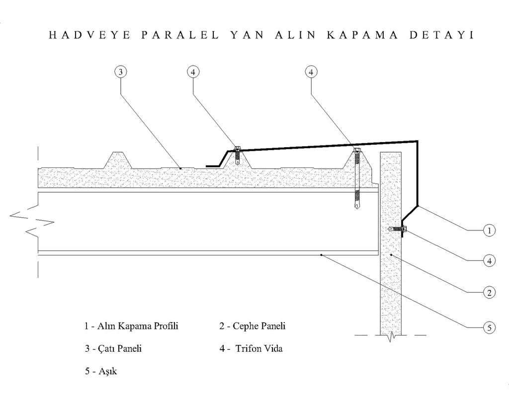
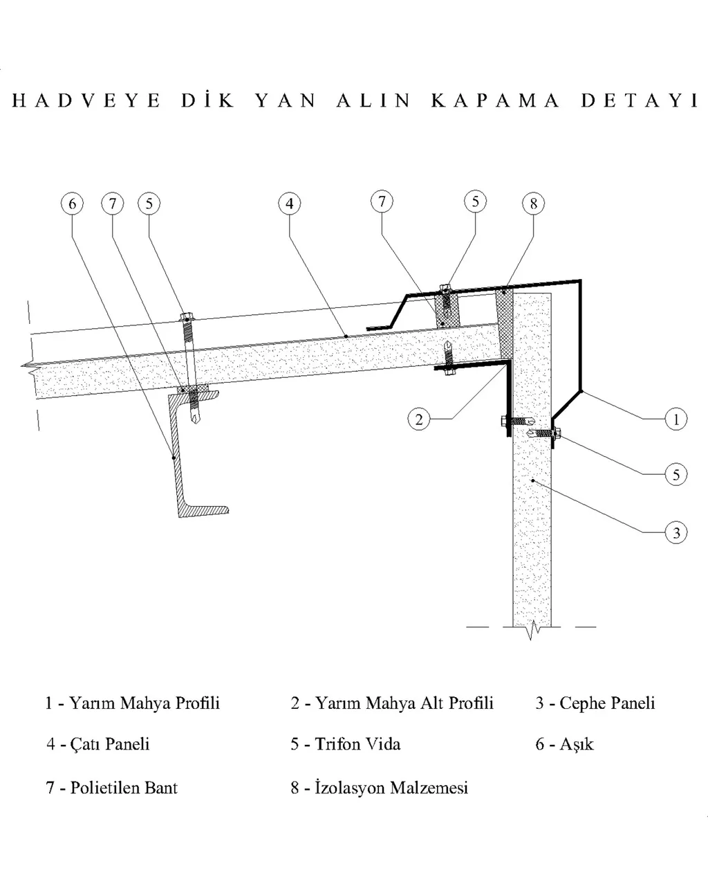
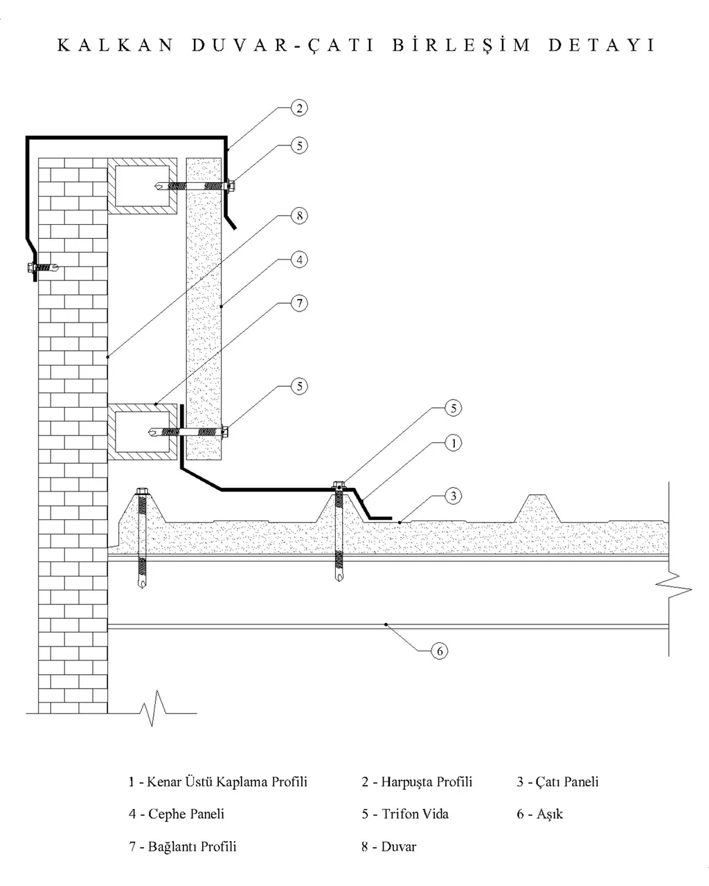
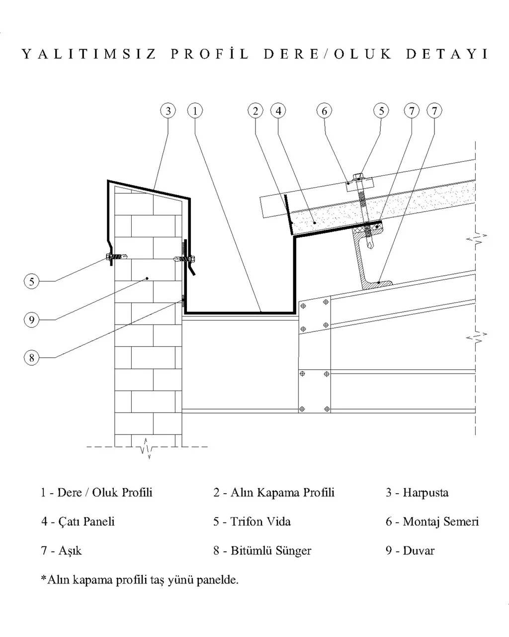
Principle Details
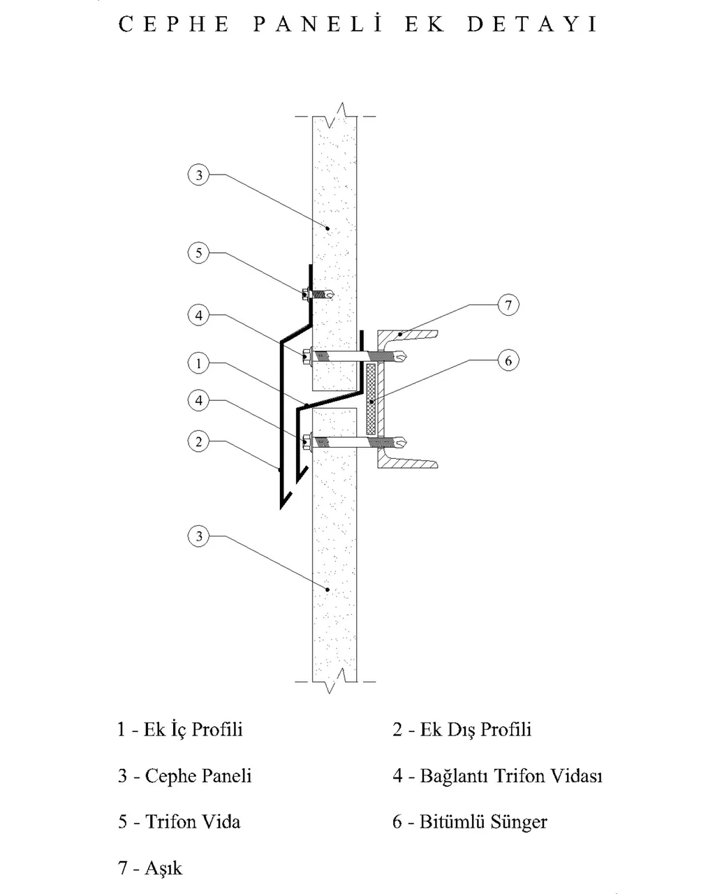
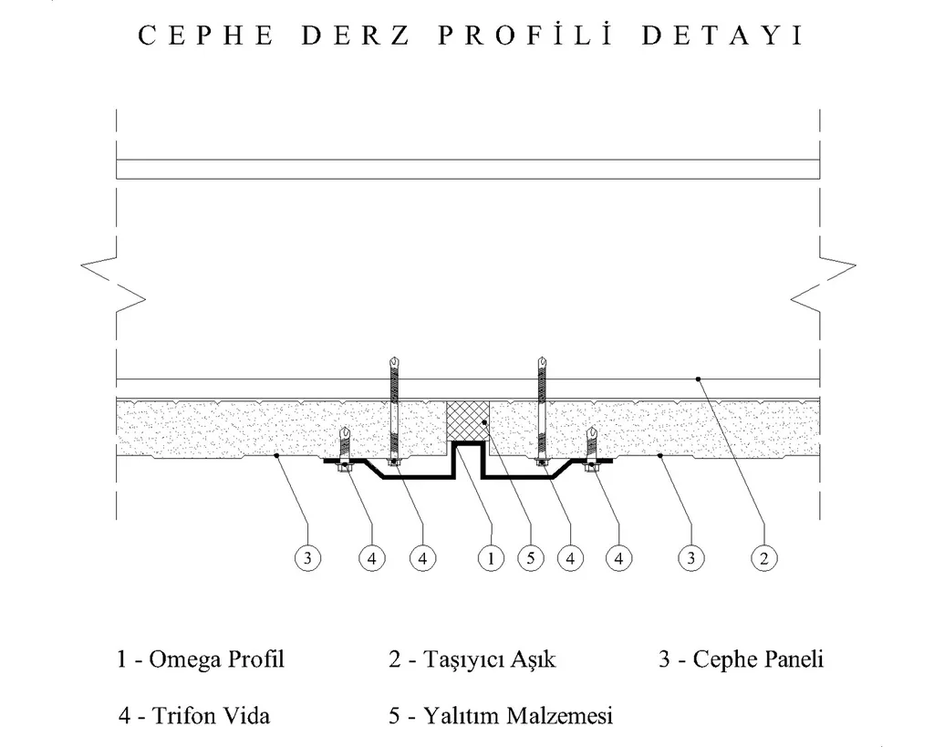
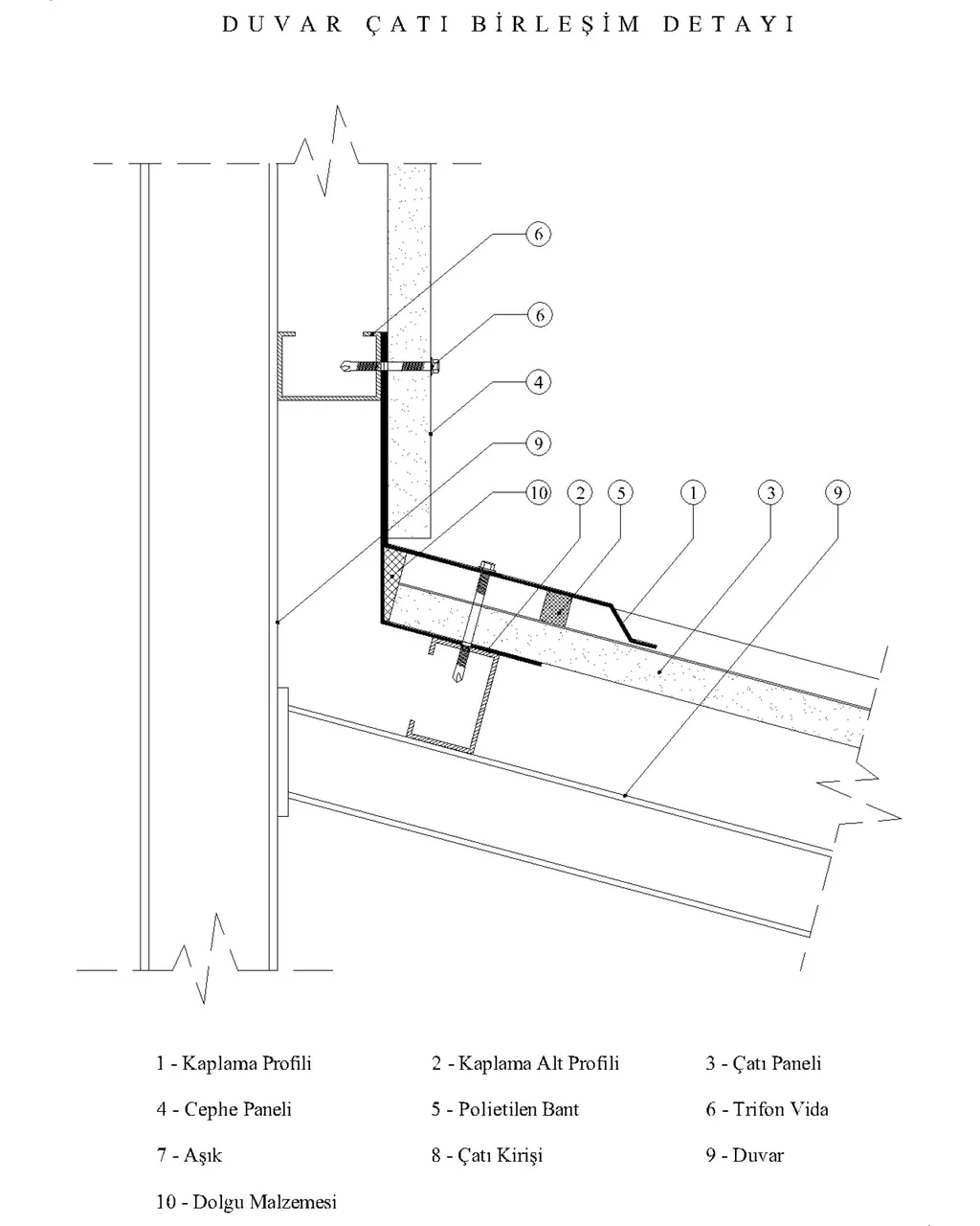
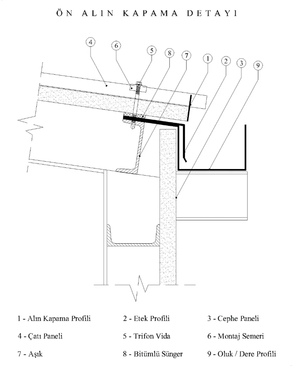
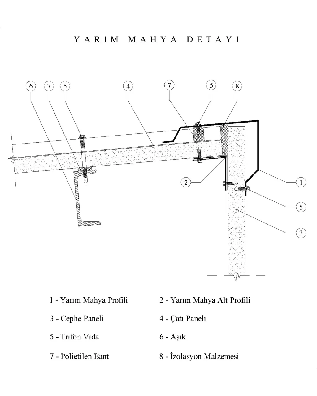
The twenty-one principle details below are the drawings given in Annex A of TS 13902.
Each drawing carries a parts key; the numbers show which profile goes where on site. Click a drawing to enlarge it.
Project-specific sections and downloadable details are in the Connection Details section.